“In the field of observation, chance favors only the prepared mind”
Louis Pasteur
Table of Contents
Definition
PFMEA stands for Process Failure Mode and Effect Analysis. PFMEA is a structured analytical tool that helps identify and prioritize potential modes of failure in a manufacturing or assembly process at the system, subsystem, or component level. Also, it helps identify ill impacts of those failures on desired outputs and what can be done, with current resources, to eliminate or reduce impacts of those failures.
PFMEA is different from Design FMEA in the sense that it focuses on the process design rather than the product design.
Any manufacturing process or service operation has some inherent errors and is not perfect. But there are certain controllable deviations that we can control. The goal is to reduce the uncertainty as much as possible.
FMEA acts as preparedness tool that helps us prepare for any kind of uncertainty we encounter in daily operations.
PFD,DFMEA,Technical documents such as drawing,Past failure history and customer specific requirements acts as inputs for PFMEA.
Actions to prevent causes,Action to detect failure modes and Action history are the expected outputs of PFMEA.
History of PFMEA
FMEA has its roots in the FMECA (Failure Mode Effect and Criticality Analysis) developed by the US military for analyzing defense systems in the late 1940s. It was first used in the 2nd world war. It was not in the form as we practice it today but one thing is for sure the concept of FMEA got its genesis from that period only.
FMEA found relevance in the Automotive field in the 1970s. It was used as Design FMEA first, after design issues encountered in Ford’s Pinto Model(Pintos had experienced moderate speed, rear-end collisions that resulted in fuel tank damage, fuel leakage, and fire occurrences that resulted in fatalities and non-fatal burn injuries)
FMEA guidelines are majorly defined by AIAG. The latest edition is the 5th edition, or we can call it the first edition of its type, as it is jointly framed by AIAG and VDA.
Why use PFMEA?
Here it is important to understand the rule of 10 to get a better perspective about the need for FMEA.
As per the rule of 10, an issue costs 10000$ when it is discovered in the field, then it may cost $1000 if discovered during the final test, or it may cost only $100 if discovered during the incoming inspection and even better it may cost only $10 if discovered during the design or process engineering phase.
What we can derive from the above-stated statement is that cost of failure increases exponentially as the product advances in the product life cycle. Hence conducting PFMEA help reduce the cost of failure. Help get it the first time right.
Who uses PFMEA?
PFMEA has been used worldwide in multiple industries such as Aerospace, Chemical process industries, Automotive, FMCG, Healthcare, etc.
PFMEA is a team activity and can’t be conducted by one person sitting in a conference room. The best approach to team formation is Cross-functional team formation.
How to Perform PFMEA?
Prerequisites
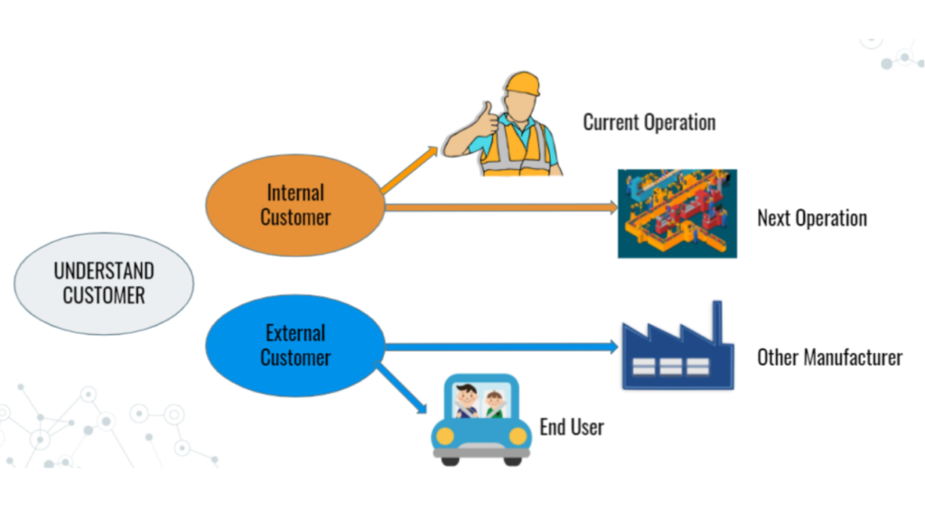
Define Customer
The definition of the customer for FMEA should normally be the “End User’‘.However, the customer can also be subsequent or downstream manufacturing or assembly operation, a service operation, or a regulator.

Team Approach
FMEA development is the responsibility of a multi-disciplinary or cross-functional team whose members encompass the necessary subject matter knowledge. This should include facilitation expertise and knowledge of the FMEA process. A Team approach is recommended to benefit the FMEA development process to ensure Input and collaboration from all affected functional areas.
The FMEA team leader should select team members with the relevant experience and necessary authority.
Team shall include the following stakeholders.
- Process Engineer
- Manufacturing Supervisor
- Operators
- Quality
- Safety
- Product engineering
- Customer
- Supplier
Design Considerations
The team should assume the product as designed will meet the design intent.
During the development of a PFMEA, the team may identify opportunities that, if implemented, would either eliminate or reduce the occurrence of a process failure mode.
For example, adding a feature to a part and a matching feature to a fixture will eliminate the possibility of an operator placing a part in the wrong orientation. Such information must be provided to the responsible design executive for consideration and possible implementation.
Step#1 Review the Process
Defining the Header of the Process FMEA

FMEA Number(A)
Enter an alphanumeric string that is used to identify the PFMEA document. This is used for document control.
Item(B)
Enter the name and number of the system, subsystem, or component for which the process is being analyzed.
System FMEA
A system FMEA is made up of various subsystems. Example systems include chassis system,powertrain system, etc. The focus of system FMEA is to address interfaces and interactions among systems, subsystems, environment, and the Customer.
Sub System FMEA
A subsystem FMEA is a subset of a system FMEA.An example of a subsystem is the front suspension subsystem which is subset of the chassis system.The focus of sub system FMEA is to address all interfaces and interactions among the subsystem components and interaction with other sub system or systems.
Component
A component assembly FMEA is a subset of a subsystem FMEA.An example would be, brake pad, it is a component of brake assembly,which is a subsystem of the Chassis system.
Process Responsibility(C)
In this segment enter the OEM, organisation,department or group who is process design responsible.Also enter the supplier organisation name,if applicable.
Model Year(s)/Program(s)(D)
Enter the intended model years and programs that will use or be affected by the process being analysed (if known).
Key Date(E)
Enter the initial FMEA due date, which should not exceed the scheduled start of production date. In case of a supply organisation, this date should not exceed the customer required Production Part Approval Process(PPAP) submission date.
FMEA Date(Orignal)(F)
Enter the date the original FMEA was completed and the latest revision date.
Core Team(G)
Enter the team members responsible for developing the PFMEA. Content information (example, name, organization, telephone number, and email) may be included in a referenced supplemental document.
Prepared By(H)
Enter the name and contact information including the organization (Company) of the Engineer/Team leader responsible for preparing the PFMEA.
PFD linkage to PFMEA
A process flowchart is a good starting point for reviewing the process. A process flow diagram describes the flow of the product through each process from incoming to outgoing. This should include each step in the manufacturing or assembly process as well as their related Outputs (Product characteristics, Deliverables, Requirements, etc). Process flow shall be detailed and not just a high-level process map.
Hence PFMEA shall be consistent with the information in the process flow diagram.In order to ensure continuity it is recommended that CFT shall Develop Process flow diagram,PFMEA and Control Plan.
Process review come in handy as :
- It makes the team familiar with the process and its elements.
- Review step ensures that all steps of the process are covered in the PFMEA.
- It is important that the team shall take a gemba walk to familiarize themselves with each element of the process.
Other sources of information those are important in providing CFT With ways to focus on the requirements of the process include:
- DFMEA
- Drawing and Design Records
- Bill of Process
- Interrelationship(Characteristics) Matrix
- Past Defect history
- Quality and Reliability History

Process Step(a1)
In this field enter the identification number or reference number of the process step being analyzed. This identification number can be as per the terminology decided in your control of documents procedure.
Process numbering scheme, sequence and terminology used should be consistent with process flow diagram,control plan and other standard documents such as operator instructions.
Process Function(a1)
Process function describes the purpose of the process step being analysed. In this step we list down the process function related to each step or operation being analyzed.
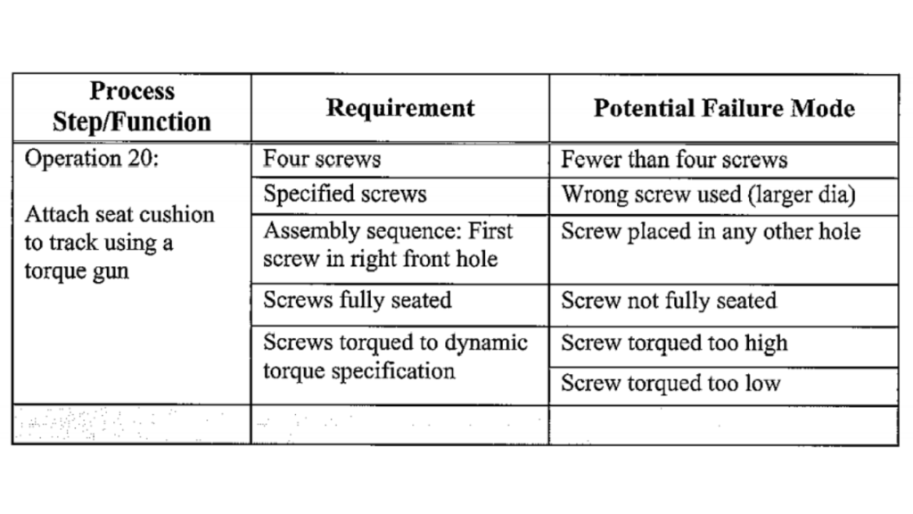
Requirements(a2)
In this step, we list the requirements for each process Function of the process step or operation being analyzed. Requirements are inputs to the process specified to meet design Intent and other Customer requirements. If there are multiple requirements with respect to a given function, each should be aligned in PFMEA with the respectively associated failure modes in order to facilitate the analysis.
Step#2 Brainstorm the potential failure modes(b)
It is important to understand the definition of failure mode to properly understand this step.
Failure Mode: A potential failure mode represents any manner in which the component or process step could fail to perform its intended function or functions.
Word Potential is used since the assumption is made that failure could happen but may not necessarily occur.
There are five failure modes:
- Full failure: The system or component is no longer functional and needs to be removed entirely due to its life cycle and be replaced.
- Partial failure: There is still some functionality, but the system or component is not operating as it should.
- Intermittent failure: Where the malfunction occurs on an irregular basis.
- Degraded failure: Frequent usage leads to fatigue which weakens the functionality of an item
- Unintentional failure: Failure from one item affects another.
In this step, we identify potential failure modes for each requirement of each element or step of the process laid out in the previous step.
If the requirements are well defined then the potential failure modes are readily identifiable by determining the condition when the specific requirement is not met.
CFT shall participate in a brainstorming session for this activity.

Step#3 List potential effects of Failure(c)
In this step we investigate what impact failure could have on the product output.Failure could have impact on final product,next process,environment,safety etc.
There can be multiple effects of a single failure and all should be covered.
Effect of failure could be based on the type of failure.Types of failure are covered in the previous step.
It is important to understand customers at this stage.Explained in Step#1.
Knowing customers can help determine the effects of related failure modes more effectively.
Potential failure modes should be described in technical terms and not as symptoms necessarily noticeable by the customer.
Important questions to answer at this stage are as follow :
- Does the potential failure mode physically prevent downstream processing or cause potential harm to equipment or operators?
- What is the potential impact on the end user?
- What needs to be done if the Failure is detected before it reaches the end user?
If we can answer these questions effectively,listing down potential effects of failure would not be a big issue.
Step#4 Assign Severity Rating(d)
Severity rating is based on the consequences of the failure,imagining what if it happens in real.Severity rating is given on the scale of 1-10.1 Being least severe and 10 being most severe.
Severity rating is generally based on product application and team experience.But general idea about rating is as follows:
Manufacturing Site Impact
- 2: Minor Disruption might slows down production (does not describe a lean operation)
- 3-6: Moderate disruption with rework out of station; additional operations required
- 7-8: Major disruption, rework and/or 100 % scrap is produced; may shutdown lines at customer or internally within the organization
- 9-10: Regulatory and safety of the station is a concern; machine / tool damage or unsafe work conditions
End User impact
- 2-4: Minor Annoyance which customers might or might not notice.
- 5-6: Loss or degradation of secondary function.
- 7-8: Loss or degradation of the primary function
- 9-10: Regulatory and safety noncompliance
Step#5 Classification(e)
This column is used for high-priority failure boards or causes that require additional engineering assessment.
This column may also be used to classify any special product or process characteristic.
Step#6 Potential Causes of Failure Mode(f)
Potential causes of failure are defined as an indication of how the failure could occur and are described in terms of something that can be corrected or controlled. Potential causes of failure are indications of design or process weakness, leading to failure mode.
Try and identify each and every potential cause possible and describe that cause in detail.
Single failure mode can have multiple causes and each shall be covered.
Errors or malfunctions shall be defined very clearly. For example, washer not assembled or washer assembled in the reverse direction). Ambiguous words or phrases shall not be used, such as washer mis-installed, etc)
Step#7 Assign Occurrence Rating(g)
Occurrence rating is based on the relative possibility of a cause of failure would occur. It is given on the scale of 1 to 10.1 means probability is least, whereas 10 means probability of occurrence is highest.
Reference to be taken from past data to decide the likelihood. If it’s a completely new part, reference shall be taken from similar part data.
Step#8 Define Current Process Controls(h)
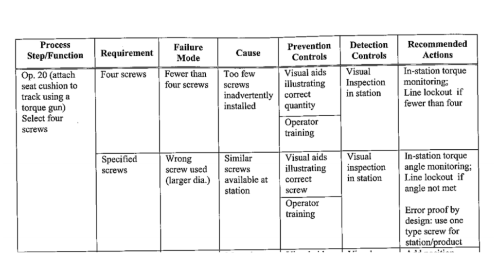
Current Process controls are descriptions of the controls that can either prevent, to the extent possible ,the cause of failure from occurring or detect the failure mode or cause of failure should it occur.
There are two types of process controls to be considered:
Prevention Control : Eliminate or prevent the cause of the failure or the failure mode from occurring,or reduce its rate of occurrence.
Detection Control : Identify or detect the cause of failure or failure mode ,leading to the development of associated corrective actions(s) or countermeasures.
Step#9 Assign Detection Rating(i)
Detection rating is the rank associated with the best detection control listed in the detection controls column.
It is also on the scale of 1-10.1 means the probability of detection is highest and 10 means the probability of detection is the least.
Ranking 1 is reserved for failure prevention through proven process design solutions.
It should not be pre-assumed that if the occurrence rating is low then the detection rating will also be low.We should assume that failure has occurred and then assess the capability of our current controls to prevent dispatch of parts with failure mode.
Step#10 Determining Action Priorities
The whole purpose of conducting a family activity is to reduce risk.
Once we have identified the potential failure modes ,effects,causes and controls,including ranking for severity detection and occurrence,we need to decide actions to reduce risks pertaining to the identified failure modes.
We as an organization or unit have limited resources,time,and other factors so we can’t take action on each and every Point.Hence we have to develop a prioritization criteria to decide where we need to take action first.
Primary focus shall be tackling high severity rating points i.e. if severity rating is 9 or 10 ,these points shall be addressed first.
For failure modes with severity 8 or lesser highest occurrence and detection rating failure modes shall be addressed.
But one thing you should keep in mind are just guidelines for minimum compliance,you can draft criteria as per your organization’s requirements.
Calculating RPN
RPN Stands for Risk Priority Number
RPN = Severity(S) X Priority(P) X Occurrence(O)
Many organizations use a threshold for the RPN number but it’s not a recommended practice as per AIAG.
Establishing RPN thresholds Promotes wrong behavior of team justifying lower occurrence or detection rating rather than concentrating on eliminating the failure mode.
Recommended Actions(k)
The intent of any recommended action shall be to reduce ranking in the following order: Severity, occurrence, and Detection
To reduce severity ranking :
Only design or process revision can bring about a reduction in the severity rating. But it is important to understand that every design or process change might not bring severity rating down. The team has to analyze and discuss the impact of design or process change on the severity rating.
To reduce Occurrence ranking :
Studies shall be conducted to understand the sources of variation in process and product.Working on reducing these variations will help reduce occurrence rating.These actions could be process or product design revisions.
To reduce Detection ranking :
The preferred method for improving detection ranking is through error or mistake-proofing. A redesign of the detection methodology may result in a reduction of detection rating.
Increasing inspection frequency is not a very effective action, it should only be used as a temporary action to collect additional data related to the process, to decide permanent actions.
If the assessment leads to no recommended action for a specific failure mode,mention “None” in the recommended action column and also describe the rationale for writing “None”.
Responsibility & Target Completion(l)
In this column, the name of the person responsible for completing each recommended action is mentioned.

Step#11 Action Results
Actions taken and actual Completion date(m)
This section includes a brief description of actions taken and the Actual Completion date for those actions.
Revised Severity,Occurrence and detection rating (n)
This section reflects revised ratings as per recommended actions.
But rating shall not be changed just based on revised actions.But check effectiveness of those actions and then only revise the rating.
When to perform PFMEA?
- PFMEA is performed when a new technology or process is introduced.
- There is a current process with modifications, which may include changes due to updated processes, continuous improvement, Kaizen, or Cost of Quality improvement.
- When the current process is exposed to a new environment or location change.
- For actions taken against internal or external customer complaints.
- Periodic review of current PFMEAs.
What are the benefits of PFMEA?
- Improves processes before failure occurs.
- Increases safety and enhances customer satisfaction.
- Improves performance monitoring.
- Decreases warranty costs, wastes,non-value-added tasks.
- Priorities resources to ensure process improvement efforts are beneficial to customers.
- Helps prioritize risks.
- Help build engineering/manufacturing knowledge base.
- Identifies critical aspects of the process.
- Acts as an important tool for continuous improvement.
- Improves process reliability.
- Reduces development time.
Resources
AIAG Manual PFMEA 4th Edition


